
Sciencetech Solar Simulators
Solar simulators are light sources with specialized characteristics that make them similar to natural sunlight in quantifiable ways. At minimum, solar simulators resemble natural sunlight in their specific spectral match, their low spatial non-uniformity, and their low temporal instability.
Solar simulators are
described in terms of their classification in the format: “Class XYZ” in which
the position of the letters is fixed:
Class XYZ: X represents spectral match: the output irradiance is measured in several wavelength intervals. The percentage output irradiance in each interval is measured, and any one interval with the lowest classification match determines the total ranking (e.g. if all intervals but one are Class A, and one is Class B, the spectral match is Class B).
Class XYZ: Y represents spatial non-uniformity: the output irradiance is measured at a set of evenly spaced points throughout the target area. The upper and lower range of those points determines the spatial non-uniformity classification. It is important to note that this parameter uses broadband measurements and does not break down the light into wavelength intervals.
Class XYZ: Z represents temporal instability: the output irradiance is measured over a specified time interval and the upper and lower range of these measurements determines the temporal instability. It is important to note that the relevant time scale for these parameters was determined with regard to silicon photovoltaics, so other applications may have different (including less stringent) requirements.
Classifications of A+, A, B, and C for each parameter are defined by internationally recognized standards. Class A+ is primarily intended for use in calibration laboratories and is not considered necessary for manufacturing and qualification testing.
Other features that are not included in the standard classification but which may nonetheless be important in specific applications include:
Collimation: the degree to which the rays of light are parallel. Due to the extreme distance between the sun and the earth’s surface, natural sunlight is highly collimated. In many applications, this is not highly relevant, but in others, especially space applications, it may be important.
Air Mass Filter: Depending on the specific conditions the solar simulator is intended to simulate, different spectral conditions will need to be adhered to. For example, greater UV output and greater overall intensity is required when simulating the environment just outside of the earth’s atmosphere (AM0) rather than simulating the environment present outdoors, on the ground, and at mid-latitudes (AM1.5G).
Terrestrial or Space Solar Simulator: Depending on the specific conditions the solar simulator is intended to simulate, different spectral conditions will need to be adhered to. For example, greater UV output and greater overall intensity is required when simulating the environment just outside of the earth’s atmosphere (space solar simulator or AM0) rather than simulating the environment present outdoors, on the ground, and at mid-latitudes (terrestrial solar simulator or AM1.5G). AM1.5D and AM1.0D are less common air masses used in terrestrial solar simulators.
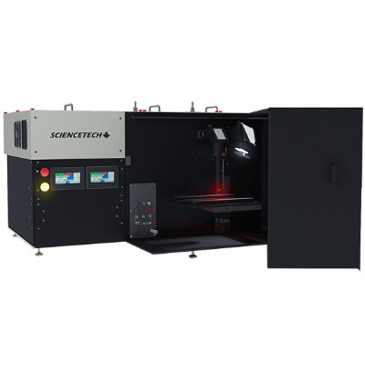
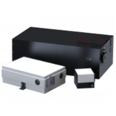
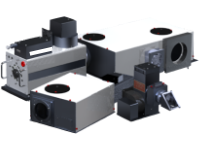
Introduction to Our Ultra-High Efficiency Solar Simulator
Class AAA UHE-NL-150
We manufacture many other varieties of solar simulators and this demonstration is applicable to our other solar simulator types as well. All the instructions in the video will also be provided in the manual that comes along with the system.
Sciencetech Webinar: Versatile Solar Simulators
Explore Unlimited Research Opportunities
This webinar is an overview of the guidelines and principles behind designing and manufacturing Solar Simulators. Discussion topics include: why use a solar simulator, how to choose the right solar simulator, solar simulation specs, and an overview of our UHE Solar Simulator.
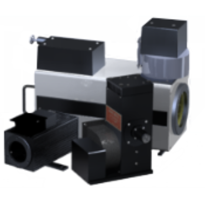
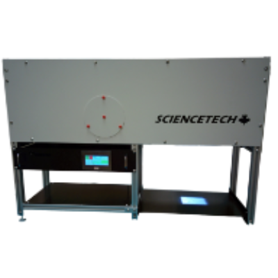
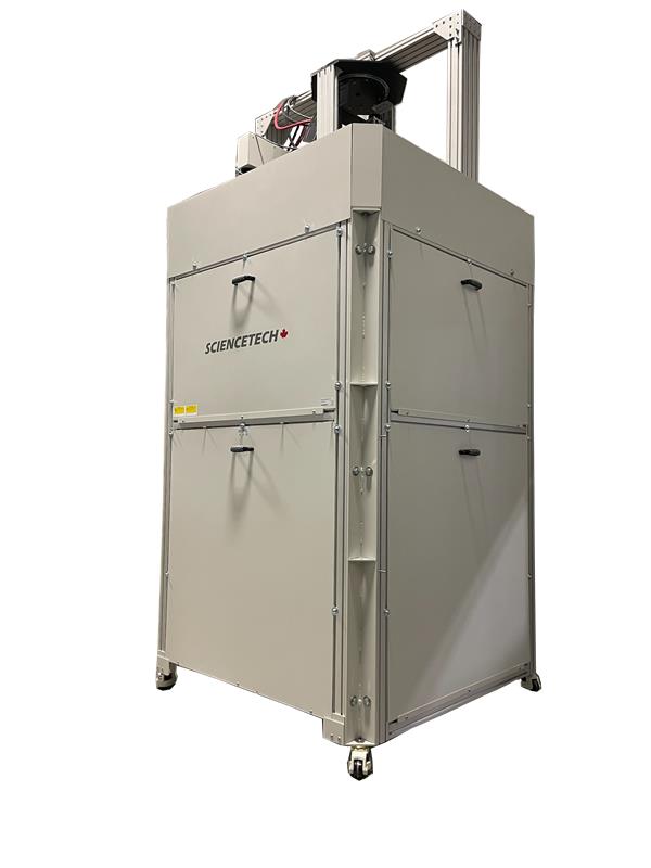
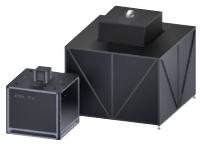
Sciencetech Solar Simulator Models
Class AAA and ABA (Spectral match, spatial non-uniformity of irradiance, temporal instability)
Sciencetech Inc. designs and fabricates more than 30 different variants of Solar Simulators. Compliance to standards IEC 60904-9, ASTM E 927 Class A spectral match, Class A or B spatial non-uniformity of irradiance, Class A temporal instability. Take a look below.
| Solar Simulators | Target Size | Working Distance | Spatial Non-Uniformity |
||||||
| Square Side | Circ. Diameter | ||||||||
| Inches | cm | Inches | cm | Inches | cm | Class | |||
| SF Class A | 0.7 | 1.8 | 1 | 2.5 | 3 - 4 | 13 | A | ||
| SF Class B | 1.4 | 3.6 | 2 | 5 | 3 - 4 | 13 | B | ||
| SciSun AM1.5G | 2 | 5 | 2 | 5 | 15 | 38 | A | ||
| SciSun AM0 | 2 | 5 | 2 | 5 | 15 | 38 | A | ||
| 2.1 | 5.2 | 3 | 7.5 | 18 | 45 | B | |||
| SS1.0kW | 3.5 | 8.8 | 5 | 12.5 | 30 | 75 | B | ||
| SS1.6K | 4.2 | 10.7 | 6 | 15.3 | 36 | 90 | B | ||
| SS2.5K | 5.6 | 14 | 7.8 | 20 | 42 | 105 | B | ||
| SS0.5kW-UV | 2.1 | 5.3 | 3 | 7.5 | 18 | 45 | B | ||
| SS1.0kW-UV | 3.5 | 8.8 | 5 | 12.5 | 35.2 | 88 | B | ||
| SS1.6kW-UV | 4.5 | 11.3 | 6.4 | 16 | 50 | 125 | B | ||
| SS2.5kW-UV | 5.6 | 14.1 | 8 | 20 | 42 | 105 | B | ||
| SFR1.6K | 6.3 | 16 | 8.5 | 21.5 | ~12 | 30 | B | ||
| SFR3.0K | 8.4 | 21 | 11.5 | 29.5 | ~12 | 30 | B | ||
|
Fiberized
(Optical Fiber) |
AX-Lightline | 2 | 5 | 2 | 5 | 16 | 40 |
A
|
|
| AX-Lightline | 1 | 2.5 | 1 | 2.5 | 8 | 20 |
A
|
||
|
UHE Work Station
(Ultra High Efficiency) |
UHE-NS-075 | 3 | 7.5 | 3 | 7.5 | 8 | 20 |
A
|
|
| UHE-NS-100 | 4 | 10 | 4 | 10 | 12 | 30 |
A
|
||
| UHE-NL-150 | 6 | 15 | 6 | 15 | 20 | 50 |
A
|
||
| UHE-NL-200 | 8 | 20 | 8 | 20 | 23 | 58 |
A
|
||
| UHE-NS-250 | 10 | 25 | 10 | 25 | 26 | 65 |
A
|
||
| UHE-NS-300 | 12 | 30 | 12 | 30 | 26 | 65 |
A
|
||
| LASI | 20 | 50 | 20 | 50 | 40 | 100 | C | ||
| PSS 1 | 40 | 100 | 40 | 100 | 3 | 7.5 | up to A | ||
| PSS 1.5 | 60 | 150 | 60 | 150 | 3 | 7.5 | B | ||
| PSS 2 | 75 | 190 | 75 | 190 | 3 | 7.5 | B | ||
|
|
FSSC 200-4000 Suns | 2 | 5 | 2 | 5 | ~0.5 | ~1.2 | A | |

The Solar Constant and Solar Simulation
The radiation from the Sun is measured in two ways for a variety of fields of research. The solar constant is the irradiance or intensity of light incident at the surface of the Earth’s atmosphere on a plane normal to the angle of incidence.
This value has been defined by the World Meteorological Organization to be 1366.7W/m2 outside the atmosphere. The irradiance of the Sun at the Earth’s surface varies under different conditions due to absorption and scattering effects in the atmosphere, and so a number of other constants are important in regards to the irradiance of a solar simulator.
| Solar Spectrum * | Filter | Power Density (mW / cm2) | Transmission % |
| In Space | AM0 | 137 | 61.3% |
| Direct Solar Spectrum at 0° Zenith Angle | AM1.0D | 104 | 67% |
| Global Solar Spectrum at 0° Zenith Angle | AM1.0G | 100 | 66.7% |
| Direct Solar Spectrum at 48.2° Zenith Angle | AM1.5D | 93 | 65% |
| Global Solar Spectrum at 48.2° Zenith Angle | AM1.5G | 100 | 58.5% |
| Direct Solar Spectrum at 60.1° Zenith Angle | AM2.0D | 71 | 57.3% |
| * All measurements at sea level, excluding AM0 | |||
The table above gives the 1 SUN irradiance values for both of Sciencetech’s filter in common simulated conditions, as well as the approximate transmission values relative to unfiltered light between 250-2500nm.
Below the atmosphere the radiation emitted from the Sun can be divided into two components: direct radiation that comes from the Sun itself, and scattered radiation coming from the rest of the sky, including a portion reflected back from the ground. Solar simulators are adjusted to imitate the spectral distribution of sunlight for a variety of environments; to do this the spectral distribution from the xenon arc lamp source is altered and refined using Air Mass (AM) filters.
When discussing filters, the direct radiation spectrum is imitated using a direct (D) filter, and the total including scattered sky and ground radiation is matched by using a global (G) filter that imitates both components together.
Sciencetech AM Filters
Sciencetech’s AM filters are designed to be used individually for standard conditions, although they can also be arranged in series to produce other spectral distributions. Many solar simulator systems used by our competition require filters to be used in series to achieve the same performance as Sciencetech’s filters, for example using AM0 and AM1.0 filters in series to achieve a AM1.0 spectral distribution, whereas Sciencetech’s AM1.0 filter can be used alone to achieve the same result, reducing power loss and the cost of additional filters.

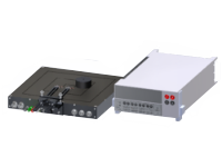
.png "Sciencetech Xenon Arc Lamp Light Source")
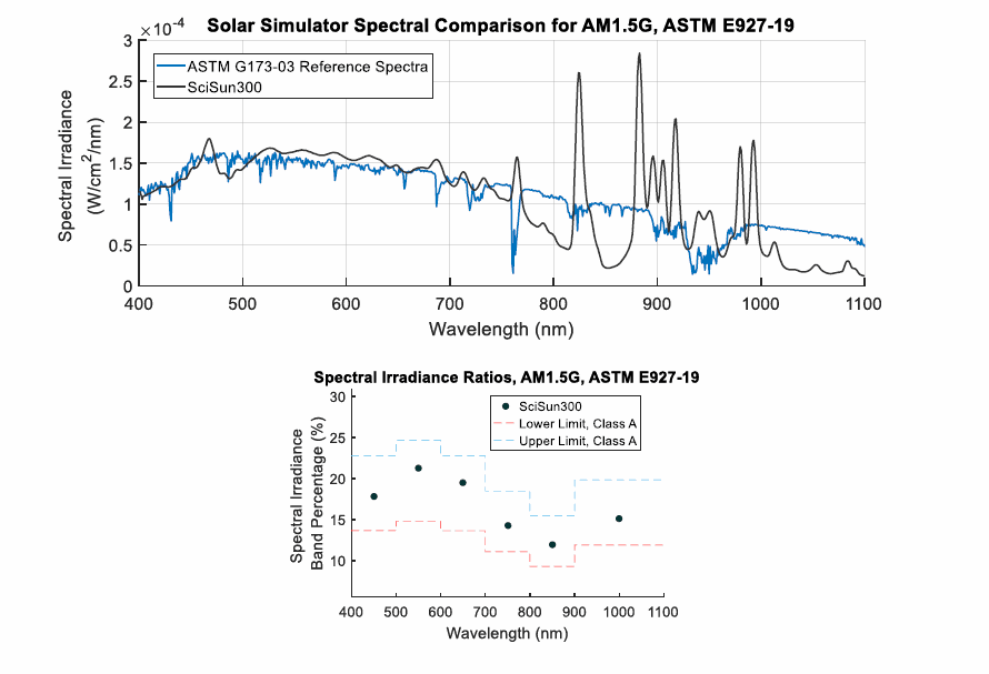
Most Sciencetech solar simulators use xenon arc lamps, which enables the system to produce an intense, collimated beam of light, similar to that of a 5,800oK blackbody. The biggest difference between the two is the xenon lines are present in the arc spectrum, and atmospheric absorptions in solar spectra, which is especially highlighted in the 800-1100 nm range because of the intense line output of the lamp. An AM0 filter can reduce this effect so that the average level in specified bands matches solar levels above the atmosphere to better than ±25%, although complete elimination of the xenon lines while preserving the rest of the spectrum is impossible with a practical filter. AM1.0, 1.5 and 2.0 filters further modify the visible and UV portions of the spectrum for different sea-level conditions, and coupled with the use of high pressure xenon arc lamps Sciencetech is capable of producing Class A standards for our solar simulators.
The graphs on the right show the typical output spectra of Sciencetech’s fully reflective solar simulators. These spectral irradiance curves combine the spectral curves of the xenon arc lamp source, air mass filter, and mirrors used inside the solar simulator beam homogenizer. Actual output spectra may vary due to the condition of the lamp and manufacturing tolerances of the air mass filters. In order to simplify visual comparison of the spectral curves of our solar simulators with ASTM E927-19 standard curves, the simulator outputs are normalized to the corresponding standard spectrum.